|
AMP gauges at the dash are
troublesome.
They should be by-passed, and then
install a VOLT gauge.
by Mark Hamilton
THE
PROBLEM
The antiquated AMP gauge system has reduced more
Dodge owners to pedestrian status than any other kind!
And (wire) “terminal illness” at firewall
connectors has also been a major problem.
(Chrysler Corp. stayed with the old AMP gauge
system long after other automakers switched to VOLT gauges,
and Dodge trucks used the AMP gauge more recently than others,
so we have used a Dodge truck as a model for this
project.)
Dodge is not the only make with concerns about
AMP gauge systems, early FORD Broncos, International SCOUT,
and many old cars and trucks used the AMP gauge system
too. But when the
electrical system will be up-graded with more powerful
alternators and more accessories, the AMP gauge should be
removed, and the “main power system” should be
modified.
With normal but frequent use, most of these Dodge
trucks will have electrical wiring problems. The first to fail were
often the trucks equipped with factory air conditioning. The air conditioning
system adds a significant electrical load. And the “air” gets
used in hot summer weather when heat will increase resistance
at connections.
The additional current flow when using the air
conditioning and increased resistance with heat will break
down the weak areas more quickly. With sufficient use,
the non-air equipped trucks will also have electrical problems
stemming from the same cause.
Typical Dodge electrical problems result from a
very antiquated power distribution system. The main source of
power for the Dodge electrical system is based upon an old
design AMP gauge at the dash and related wiring system. It’s a system that
worked okay with a very small electrical system on Model A
Fords way back in the late 1920’s. But the old
AMP-gauge-at-the-dash system is not reliable with increased
current loads of the more modern electrical system.
Compounding the situation, the wiring system for
the AMP gauge actually became weaker than it was over fifty
years earlier.
Assembly line labor was not so expensive in early years
of the car.
Affordable labor could consistently connect wires with
“ring terminals” at screws or studs with nuts–resulting with
reliable (low resistance) connections. With increased labor
cost mandating fast moving assembly lines, and many more
wiring circuits to install, “click together” connections have
been widely used since back in the 1950’s. And by the 1960’s,
even the AMP gauge (heavy current load circuit) was routed
through a “click together” connection. The least reliable of
“click together” connections for a heavy current load circuit
is the male/female flat blade terminal design. And it happens that
Dodge was built with this terminal design, even at the main
power delivery circuit.
In summary, the AMP gauge and related wiring
found in Dodge trucks of the sixties and seventies period was
built with a recipe for failure. A 70amp alternator
supporting powerful electrical accessories was typical
equipment by 1979, and the load was too much for the method of
wiring construction used. Naturally, it’s a
system that often reduced Dodge owners to pedestrian
status.
This feature clearly explains the shortcomings of using
the old, traditional, AMP gauge at the dash. And largely because of
the circuit design shortcomings, the best choice of gauge to
monitor the electrical system is a “VOLT” rather than AMP
gauge. A good
explanation of the AMP vs. VOLT gauge may be found at
http://www.autometer.com/
in the Tech Tips / FAQ section of the web sight.
THE HISTORY
In some
ways, the Chrysler Corporation was pretty far advanced where
electrical systems were concerned. (Chrysler gave us the
Dodge, Plymouth and Chrysler line, and nowadays they all may
be referred to as MOPAR.) Back in the early
‘60’s, MOPAR was the first to give us alternators rather than
the older technology generators–Indeed the improvement was
great. GM
followed, and then Ford finally installed alternators as
“standard equipment” on ’65 models.
1964
year model Chrysler products showed up with “Fusible Link
wires” for reliable short-circuit protection of the main power
circuit from the battery to the electrical system. Chevy didn’t use
Fusible Link wires until ’66 models.
And
Ford didn’t use Fusible Links until some years after GM.
Chrysler/Dodge/Plymouth
introduced a very good electronic ignition system with 1971
models. Ford
introduced a somewhat less reliable electronic ignition with
only some of their ’74 models. And GM gave us a very
good electronic ignition with ’75 models.
In
spite of being the first to give us “break through” technology
with components, it seems that the “DODGE BOYS” were reluctant
to depart from a very antiquated wiring system. The old, traditional,
“full current load type” AMP-GAUGE-AT-THE-DASH and related
wiring system was still in use with ’79 Dodge trucks. The AMP gauge circuit
wiring had to deliver electrical current used by the entire
electrical system, plus handle current to recharge the
battery. The
problem was that current load and the alternator output rating
was a large amount by the end of the ‘70’s. Alternators with about
a seventy amp available output were standard with
air-conditioned models.
And a weak terminal design was used where the AMP gauge
wiring passed through the firewall. The large demand for
electrical current often resulted with failures in the lengthy
AMP gauge circuit, even in vehicles that were relatively
new.
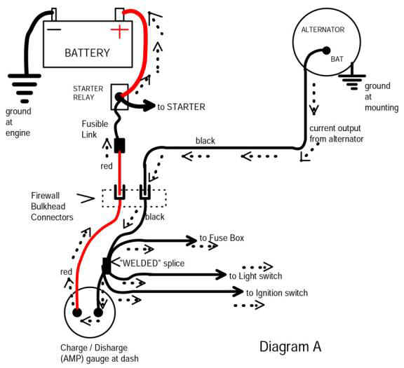
The original AMP gauge system
served as the main power distribution system. This circuit is the
power source for the entire electrical system. (see diagram
A)
Amp
gauges at the dash were standard equipment with Model A Fords,
back in the late 1920’s.
And the fifteen amp capacity gauge at the dash worked
fine with minimal electrical systems of that period. Current output from
the small Model A generators was not even sufficient to
support sealed beam headlights. (The old Model A was
equipped with a small light bulb backed up by a large
reflector in the headlight assembly.) The Model A only had
one tail/brake light at the rear, a simple ignition system and
a small battery about completed the electrical system. Such a small amount of
electrical current flow through good connections at the AMP
gauge wiring was no problem with the Model A Ford. And with current
output limited by a cutout relay on the generator, the AMP
gauge could handle the small battery charge rate. But as electrical
systems became more powerful, Ford discontinued the old AMP
gauge system long before the ‘70’s.
GM
also up-graded their system long before the Dodge Boys. When GM introduced the
alternator with ’63 models, it was controlled by a more
complicated but more efficient voltage regulator system. And the new GM system
could support a warning light at the dash. The warning light was
often standard equipment and the gauge was an option. GM
vehicles built with the gauge option also had a more modern
design of AMP gauge at the dash. The newer AMP gauge
was a remote shunt type design–a length of the battery
charging wire in the under-hood harness served as the
shunt. The dash
gauge and related wiring no longer handled heavy current
load. Same with
Ford in ’65 and newer model cars–the Ford system could work
with a warning light at the dash, and cars that came dash
gauges had a remote shunt type amp gauge.
The
Dodge alternator/voltage regulator system
had no provision to operate a warning light. And Dodge (trucks)
stuck with the old antiquated “full load type” AMP gauge
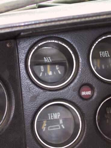
design, at least into the late 1980 models. As is typical of Dodge
trucks that were used a lot, the AMP gauge in this ’76 Dodge
was burned out.
The plastic mounting area behind the dash is completely
melted, and the lens and plastic trim is shriveled too. (This gauge is
included in Diagram A.)
Amperage
is a measure of current flow, and all of the current used to
recharge the battery was routed through this gauge–which
caused the gauge to display the battery charge rate. Both the alternator
and the battery were mounted up front, under the hood. And the AMP gauge was
at the dash. It
was an arrangement resulting with a very long wire circuit
charging the battery.
Large amounts of current flow through the AMP gauge
will generate some heat too. The plastic cover at
this gauge was only distorted by heat–but some Dodges have
sizable holes burned in the dash where the AMP gauge used to
be. Apparently,
the shunt in the gauge has a sufficient amount of resistance
to generate a damaging amount of heat with battery charging
current flow.
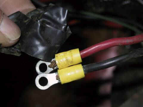
A
previous owner had replaced the terminals at the back of the
AMP gauge, and then did a weak by-pass of the gauge by taping
the two wire terminals together.
(No doubt an attempt to get the old Dodge up and
running.)
It’s fairly common to find the wires disconnected from
the gauge, and a machine screw and nut clamping the terminals
together, and finished by wrapping the screw and terminals
with tape.

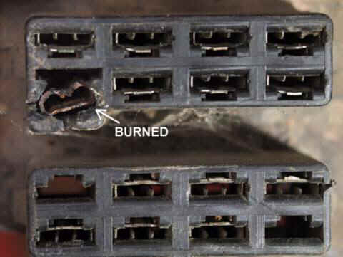
The AMP gauge wiring passed
through the “firewall bulkhead connector,” where standard,
.250 inch wide, male/female flat blade connectors were
used. (This
connection is shown in Diagram A.) These terminals were
reliable with circuits of much less current flow, as with turn
signal, clearance lights, and temp or fuel gauges. But the design was
certainly not up to the job of handling the entire alternator
output. This was
a problem spot in the AMP gauge system that often made Dodge
owners walk.
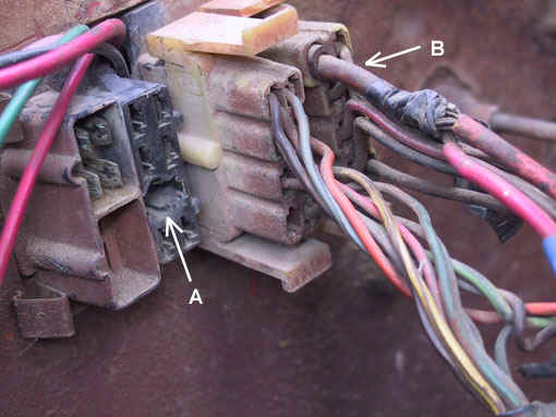
Arrow A in the photo at the
left points out a melted cavity in the plastic connector body,
where a case of “terminal meltdown” occurred. This connection served
as a pass-through for the main wire from the alternator to the
dash area. When
driving, the entire electrical system current load will pass
through this connector.
(Also seen in Diagram A.) Ignition, lighting,
heater fan, accessories, and electrical power in general flows
through the connector. The wire color code is black at this
circuit, and this model was equipped with 10 gauge wire. (Many earlier models
had only a 12 gauge black wire.)
Arrow B points out the red, 10 gauge,
battery charging wire.
After removing
the connector with the red 10 gauge battery charging wire, a
close inspection revealed that this side of the AMP gauge
circuit was also suffering from a case of “terminal
illness.” (See
arrow in photo at the left. This is the terminal
used by the 10 gauge red wire at arrow “B,” above.))
The plastic connector body
surrounding the female flat blade terminal is beginning to
melt away. And
severe oxidation of the terminal itself is evidence that this
terminal has been glowing hot. Notice that the other
terminals in the connector body are still in good
condition. The
rusty appearance of this terminal is typical of wire terminals
that have been hot while handling large amounts of current
flow. (If
moisture had caused the oxidation, all the terminals would
have been corroded.)
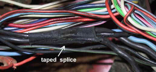
We have opened part of the dash wire harness, to show
the factory “welded splice” where wires branch off to the
ignition switch, light switch, and the fuse box.
(This splice is shown in Diagram A.)
The “welded splice” is insulated by a factory
installed, sticky cloth tape.

The
original tape has been removed for this photo to expose the
“welded spice.”
Pressure and heat fused
the copper wire strands together when making the splice. The method seems to be
reliable, as in thirty years of workshop experience the author
has never seen a failure with this splice. When electrical power
loss occurs, this is certainly not the first place to look for
the problem.

Click
here to see Part 2, where we
will by-pass the gauge and repair the wiring
|