Part
Two – AMP gauge
WIRING FIXES
(Dodge was used for this
work shop model)
By Mark Hamilton
We have seen the weak areas, now we will make
improvements. The
male/female flat blade terminals for the AMP gauge wires at
the firewall connector will be eliminated–because they are the
weakest link in the system. The AMP gauge will be
disconnected and by-passed–because the gauge often fails and
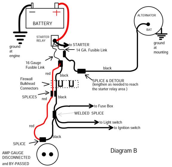
sometimes it burns dashes. Alternator output will
be routed directly to the BAT. POS. stud at the starter
relay–because it’s the most direct routing of power. And, we will make use
of both legs of the old AMP gauge circuit–because it doubles
the strength of the main power-up circuit to the “welded
splice,” which serves as power distribution.
When everything is working properly, the alternator is
the source of power to the entire electrical system. With this new system,
we have alternator output delivered to the BATTERY POSITIVE
stud at the starter relay. The stud at the
starter relay now becomes the “main buss” for power
distribution.
Battery charging current will flow directly to the
battery, via the positive battery cable. The “welded splice” in
the dash wire harness still serves as a junction for power
distribution–but now we are sending power to the “welded
splice” through both of the existing wires that were part of
the old AMP gauge system. And the AMP gauge is
by-passed.
The system
mostly uses existing wires that were already in the wire
harness. But
since we are disconnecting, bypassing, and ignoring the AMP
gauge, we can rearrange the wires to form a much stronger
system. The
male/female terminals at the firewall connector are also
by-passed, the wires now pass directly through connector body
connection.
We
have also used the proper Fusible Link wires for short circuit
protection. A 14
gauge Fusible link is protecting the 10 black wire circuit to
the alternator.
And a 16 gauge Fusible link protects the power-up wires
to the “welded splice,” which serves as main power
distribution to the dash area.
Craftsmanship and wire splicing methods will be
critically important to reliability with the new system. We are working on
wiring that must handle large amounts of electrical power
every time the truck is driven. Our work has to be
good or the outcome will be no better than the weak factory
system. We have
to use a few splices to complete the up-grade, and splicing is
a job that not everyone does well. Resistance at all
spices and connections must be minimized. Crimp-on butt
connectors with yellow plastic insulation, wire nuts, or
twisting and tapping wire together will not be reliable
splicing methods.
The old method of crimp first, then solder, then
insulate is still the most reliable.
The best parts for the job are
non-insulated butt connectors, which are made of copper and
are tinned with solder.
Good quality shrinkable tubing will insulate the
splice, and a length of it must be slipped down the wire
before installing the butt connector. We will also need a
soldering gun or soldering iron, and a lead/tin rosin core
solder.
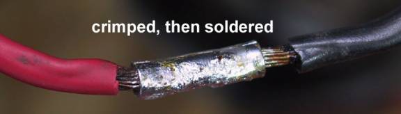
After stripping the ends of
the wires, we slipped shrinkable tubing down the wire. Then we
crimped the non-insulated butt connector onto
the wires. And
then soldered the
connection.
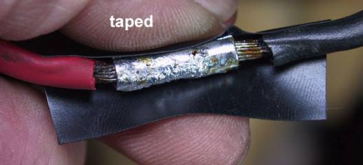
Electrical tape
may be used for the first layer of insulation, before slipping
the shrinkable tubing into place. (We are using this
option because it provides a little extra padding and
insulation over the splice.)
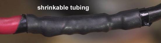
Then slide the shrinkable tubing into place, and apply
heat to shrink the tubing tightly for a good seal.
A disposable lighter works well when there is no
breeze.
A heat gun works very well and is safer too, as it is
flameless.
Hair driers do not produce enough heat to activate the
better shrinkable tubing. (The splice shown in the photos
above is where we have disconnected and by-passed the AMP
gauge at the dash.)
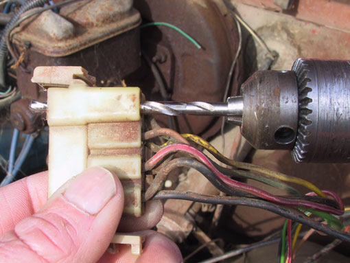
Using a drill slightly
larger than the O.D. of a 10 gauge wire, we are drilling out
one of the slots in the engine side of the firewall connector
body. A new wire
will pass directly through the connector body without the weak
male/female terminal arrangement.
Both
sides of the bulkhead connector must be drilled–the engine
side and the dash wire harness side.

In the photo above, we are drilling out the dash
harness side of the bulkhead connector. Before drilling this
side, check from under the dash to be sure that wires are
clear at the backside.
And drill just deep enough to go through the
connector–there are many wires at the other side, which could
be damaged by the drill.
This
connector body is easily dismounted from the firewall by
releasing the latches.
Removing the connector body and then dragging it under
the dash will allow drilling it from the other side. With either method, be
sure to get the correct slot so that the holes in both of the
connector bodies will be aligned after assembly.
Often the old terminal is melted into the plastic
connector body and tightly embedded. If the terminal cannot
be removed without breaking the connector body, then we can
use available unused slots for the new direct
pass-through.
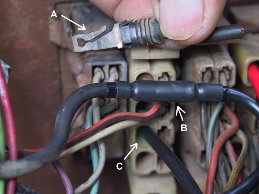
We have cut the original 10
gauge black wire from the alternator to the connector, and
then removed the terminal with wire remnant from the connector
body. (see
arrow A)
Splicing on a
new length of wire has lengthened the original alternator
output wire. Now
it is routed to the starter relay, where a fusible link will
be installed.
(Arrow B points to the splice.)
At
the dash side of the firewall connector, we also cut the wire
and removed the terminal from the connector body. And we lengthened the
wire at the dash side–it now passes directly through the
drilled out connector bodies. (see arrow
C)
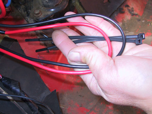
At the dash side of the
firewall connector, we have cut and lengthened the red and
black 10 gauge wires.
Both have been left long enough to pass through the
holes drilled in the connector body and reach out to the
starter relay area.
Plus we added an extra 12 to 15 inches in length, which
will be bundled to the dash harness.

The extra length bundled at the dash side of the wires
will provide opportunity for service work.
Should we ever need to inspect, test, or clean other
terminals at the connectors, we can always remove the nylon
ties and drag the extra length of wire through the connector
bodies.
Then the engine side connector body may be unlatched
and slipped over the 10 gauge wire for access to terminals in
the connector.

The photo
at left shows the fusible Link installations, where the new
wires will connect to the battery positive stud at the starter
relay.
The red and black 10 gauge wires connect
to a 16 gauge fusible link wire, which is actually identified
as a metric size on this particular fusible link. (1.0 sq mm is the
metric equivalent of 16 American
Wire Gauge size.) This circuit powers up
the welded splice in the dash harness, which powers up all
switches, fuses, and circuits at the entire dash area.
Short-circuit protection for the black 10 gauge
wire to the alternator is provided by a 14 gauge fusible link
(the light colored of the two, which is actually a 2.0 sq mm
metric equivalent.)
The up-grade really is quite simple, and it does
provide remarkable improvements to reliability and electrical
system performance.
The Dodge alternator/voltage regulator system will
perform well with the up-grade. Expect more consistent
voltage throughout the system as resistance is significantly
reduced at the main power wiring.
Craftsmanship
will have to be good, for the new system to be reliable. We are working with
the main power delivery to the entire electrical system. Current to operate the
entire system will flow from the alternator, through this
circuit, every time the vehicle is driven.
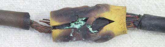
Crimp-on connectors
will not be good enough!
They are prone to “Thermal Run-away” problems, which is
exactly what happened to the crimped on butt connector shown
in the above photo.
M.A.D. offers very
quality non-insulated terminals made of “tinned” (solder
coated) copper, which are perfect for the crimp first, then
solder, then insulate with shrinkable tubing connections. (As with the splice
that shown in this feature.)
The “tech is made
simple” book, also available in through the M.A.D.
catalog, teaches splicing and soldering techniques, all about
the “Thermal Runaway” problem, and all about Fusible Link
wires.
And the M.A.D. catalog
offers excellent wire strippers and terminal crimping tool,
ideally suited for this kind of work.
|