How to build modern Traction Bars
For leaf spring cars and trucks
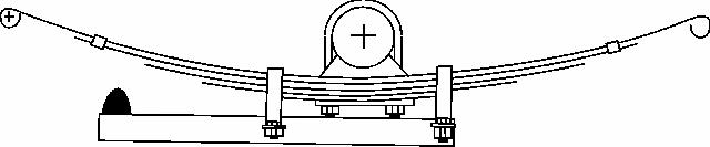
Traction devices have been around for years. Perhaps the
best known are the classic "traction bars" that bolt to the bottom of
the springs and / or axle. As the axle tries to rotate under
acceleration, these bars contact the underside of the spring and help
stop the pinion gear from trying to climb the ring gear and in the
process provide a modest increase in traction. See figure 1. Although
these devices aren't 100% effective they do work pretty well.
Figure 1
On a street rod or vehicle that may have less ground
clearance than your ordinary muscle car this type of traction bar may
present a serious problem. Not only in ground clearance but these bars
can stiffen the suspension considerably and provide less comfort for
the passengers.
Theory
When it comes to a streetable traction device what is needed
is something that limits wheel hop, prevents spring and axle wrap, and
increases traction. But that's not enough, it still has to allow the
suspension to move and work as designed so comfort and derivability
aren't adversely effected.
Perhaps the best idea so far is what has commonly become
known as "Caltrac Traction Bars". Caltracs are made by Calvert Racing a
company in Lancaster, California and represent probably the most cost
effective way to transfer the rotational energy created by the axle to
down force on the suspension which definitely improves traction. This
design transfers this rotational energy through a bellcrank system and
actually pushes down on the spring instead of up as on the classic
traction bars of the past.
Since they are generally designed for high horsepower
applications, Caltracs are very heavy-duty devices and can in this
writer's opinion be rather expensive. Since most of us aren't driving a
600 + hp Sportsman Class race car on the street, at least not for
everyday driving, we don't need the "heavy duty" aspects of Caltracs
but we still want all the benefits they provide. The solution is
simple.
Building your own version of the classic Caltrac design
isn't as hard as you may think and it only requires the basic tools any
"gearhead" will have around the garage and chances are if you don't
have what you need, you have a friend who does. Now I'll be the first
to admit that I'm no engineer but I do know what works. This system has
been proven by some pretty big names in pro-stock drag racing and
that's more than enough proof that this concept works very well.
How they work
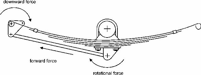
Before we get started let's look at what these bars are designed to do. (See figure 2)
Figure 2
Under acceleration the axle naturally tries to rotate. This
"climbing of the pinion gear on the ring gear changes the pinion angle
and general geometry of the suspension. In many cases it causes the
spring to deflect or "wrap up" (see figure 3) which increases the
change in pinion angle (among other things) and complicates matters
even more.
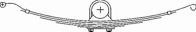
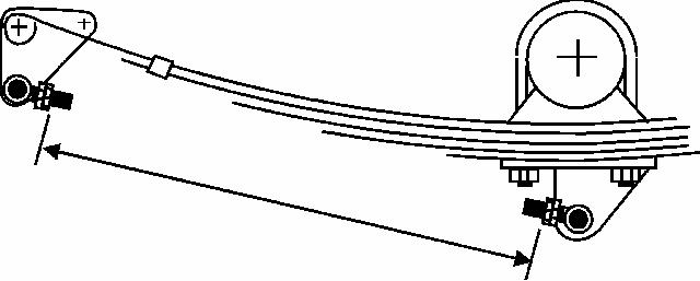
Figure 3
To effectively eliminate these problems the rotational force
of the axle must be redirected or transformed to a force that helps
weight transfer and traction. This bellcrank and rod traction system
directs the rotational energy created by the axle through a rod to a
bellcrank located on the front spring eye. There the energy is
converted to down force on the front of the spring where it is weakest.
This eliminates spring wrap and at the same time helps to force the
suspension to the ground providing an increase in available traction.
Simple but extremely effective.
Tools and Materials
You'll need a grinder, saws-all or similar device for
cutting 3/16" steel plate, a welder, and a good drill or small drill
press. Materials are easy. Just run down to your local scrap metal yard
and pick up a piece of 3/16" steel plate about a 1'x 2' and 8 feet of
ľ" ID (1"OD) steel pipe. You will also need about one foot of 5/16" ID
steel pipe. To connect the brackets and bellcrank you'll need (4) ľ"
rod ends and 8 matching nuts along with a total of at least (4) ľ"
bolts and nuts, (8) ľ" washers along with (2) 5/16" bolts, nuts and 4
washers. The length of these bolts will be determined by your specific
application so it's best to make the brackets first and then measure
for bolt length once you test fit them on the car. The big advantage of
building your own traction bars is obvious. It can easily be done in a
weekend and the cost will be well under a hundred bucks. Not bad when
you consider the price of the real thing.
Construction
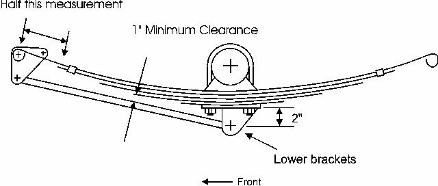
The first brackets you need to make are for mounting the
force transfer rods to the bottom of the spring retaining plates. (See
figure 4) On most applications mounting the rod at a point 2" below the
plate should allow enough clearance for the rod to connect to the front
bellcrank without interfering with the spring. Be sure to check this
before spending the time to make brackets that might be too short.
Start by measuring the distance from the front spring eye to the first
spring. Take half of that measurement and it will tell you how far
below the spring eye bolt the rod will attach to the bellcrank. On
average this measurement will be in the neighborhood of 6". The rod
should be able to miss the springs by at least 1". If it doesn't, these
lower brackets will need to be a little longer.
Figure 4
You will need to make four of these brackets and drill
a ľ" hole in each. They will be welded to the bottom of the spring
mounting plate with the attachment hole directly centered under the
axle.
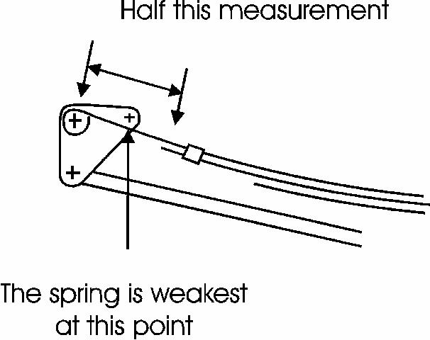
Now we need to turn our attention to the bellcrank. You'll
need four identical pieces here too. The first thing you need to do for
the bellcrank is to determine where the spring is going to deflect or
wrap up the most. In this case use the same measurement you used
previously. Half of the distance from the front spring eye to the first
spring. This is the spot where the spring is a single leaf and is
weakest and this is where you want to put down force on the spring to
keep it from wrapping up under acceleration. See figure 5.
Figure 5
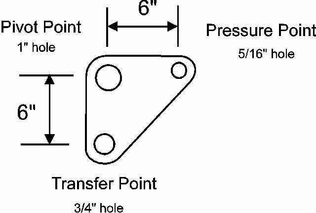
To keep the forces equal the bottom hole of the bellcrank
should be the same distance from the pivot point as the pressure point.
In this example the measurement from the spring eye to the second
spring was 12". We use half that measurement (6") to determine the
length of our bellcrank. (See figure 6) Don't forget that you need 4
identical brackets.
Figure 6
The transfer point hole needs to be ľ" to accept the rod end
and the pressure point hole should be a minimum of 5/8". In our example
the pivot hole diameter should be 1" because the current bolt size is
3/4" and we'll be using a piece of scrap 3/4" ID (1" OD) tubing left
over from cutting the transfer rods to length as bearings for the
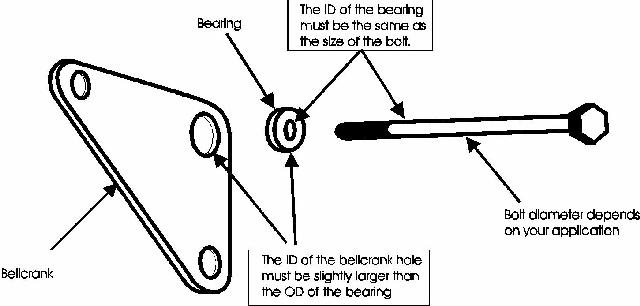
bellcrank. Your application might be slightly different so the hole
size you drill in the bellcrank might be smaller. What you are shooting
for is to use a small piece of tubing with the same ID as your bolt to
act as a bearing for the bellcrank. If your bolt is 9/16" then use that
size ID tubing for the bearing and drill the hole in the bellcrank the
same diameter as the outside diameter of the tubing you're using. The
fit doesn't have to be exact but you don't want very much slop either.
See figure 7.
Figure 7
Once all the brackets are completed, weld the small brackets
to the lower spring mounting plates with the ľ" hole centered under the
axle and from side to side. Remember to leave enough space between each
bracket to mount the ľ" rod end and a washer on each side. Don't forget
these washers, they're important. The best method I've found is to
temporarily mount a rod end with its two washers and tack weld the
brackets in place. Then remove the rod end and finish welding the
brackets. It is easier to remove the mounting plates for this job but
it can be done on the car if you don't mind welding in that position.
When you're done the lower spring mounting plate should look something
like this. (See figure 8)
Figure 8
Now we'll turn our attention to the bellcrank. First remove
the bolt and nut holding the front spring hanger in position. This will
usually require a jack under the frame to remove any tension that may
be on the bolt. Once its removed you'll have to replace it with one
that is at least ľ" longer. The bellcrank assembly will go into
position using a small piece of 1" OD thick wall tubing (the same stuff
you bought for the actuator rods) and a couple of washers on each side
so you need to make room for those with a longer bolt.
Cut four pieces of 1"OD tubing Ľ" to 5/16" thick. These
pieces will act as a bearing for the bellcrank brackets to rotate. Make
sure these pieces are thicker than your bellcrank material and that
they fit in the 1" hole in the bellcrank with little or no slop. See
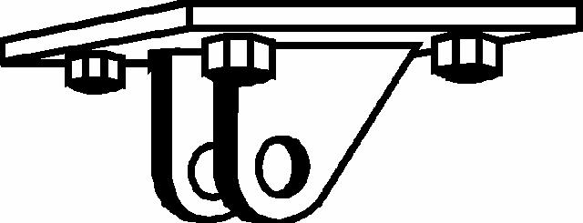
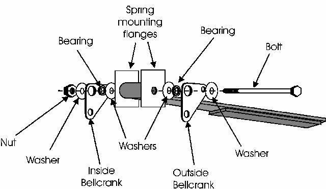
Figure 9 for proper assembly of the bellcrank.
Figure 9
When the assembly is complete the two halves of the
bellcrank should be able to rotate with little or no effort. The small
pieces of 1"ID tubing and the bellcrank bracket should be sanwiched
between two washers and the whole thing bolted through the spring eye
bolt hole.
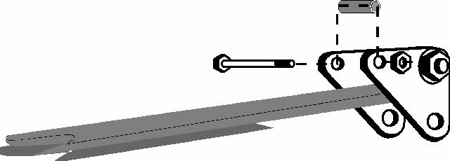
Once the bellcrank brackets are bolted in place you can cut
your 5/16 ID tubing to length. This tubing runs between the front holes
of the bellcrank and above the spring. It is secured by a 5/16" bolt
and nut. Remember just the same as the other bolts the length will
depend on your particular application. Figure 10 shows how this goes
together.
Figure 10
Transfer Rod
At this point all that remains is to assemble the transfer
rod and rod ends. The transfer rod is made of the same 1" OD (3/4" ID)
tubing you used for a bearing on the bellcrank brackets.
First you'll need to install two bolts on each of two rod
ends. Run the bolts up till there is about ˝" of thread remaining. One
bolt will eventually be welded to the transfer rod and the other will
be used as a lock nut. Now temporarily install the rod ends in their
respective brackets with ľ" bolts and nuts. Don't worry about the
washers yet, this is just temporary. Measure the distance between the
lower bolts on each rod end and you will have the measurement for your
transfer rod. See figure 11. It is very important that the bellcrank
pressure bar (the part you just previously installed) be resting on top
of the spring when you take this measurement.
Figure 11
Once you have the two transfer rods the right size weld one
of the rod end nuts on each end of the bar. The best way to do this is
to thread one all the way up one rod end, slide the rod end into the
tubing and tack the nut in place on opposite sides of the tube. Unscrew
the rod end before it gets too hot and finish welding the bolt to the
tube. Do this on each end. When you're done thread a bolt on each rod
end up to the top of the threads and then screw the rod end into the
nut on the end of the tubing.
First bolt one end of the transfer rod to the brackets on
the axle retaining plate. Don't forget to use a ľ" washer on each side
of the rod end (inside the brackets). This is important for proper
movement.
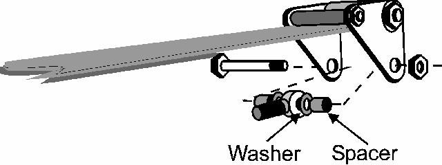
To install the bellcrank end of the transfer rod you have to
cut a couple spacers first. Measure the thickness of a rod end plus two
washers. Then measure the inside distance between the two sides of the
bellcrank at the mounting location. Subtract the width of the rod end
and washers from this measurement and divide the answer by two. As an
example… if the measurement between the two halves of the bellcrank is
5" and the thickness of the rod end plus two washers is 1", the
difference is 4". Divide by 2 and you have 2". This is the size of your
spacers. Cut the spacers (you'll need 4 total) from scrap ľ" ID tubing.
These spacers will keep the rod end centered in the bracket. See figure
12.
Figure 12
At this point you're installation should be complete.
Remember to adjust the transfer rod so the pressure point is just
resting on the spring. Do this with the weight off the wheels for best
results and once adjusted don't forget to tighten the lock nuts on all
the rod ends.
There you have it. For less than a hundred bucks in
materials you can solve almost any spring wrap or traction problem you
may be experiencing. This is not meant to be the only way or even the
best way to tackle this problem, just the way I decided to do it. I
sincerely believe that in all but the most severe racing conditions
this setup will serve you well. However, if you have a mega horsepower
big block powered street machine, I suggest you spring for the real
thing. These bars are not designed for heavy duty racing conditions but
for a street rod, they should be more than adequate. Good luck with
your installation.