![]() We’re
always amazed at the percentage of old Mopars cruising around with a
2-1/2-gallon can of gas in the trunk. Why? 9 out of 10, it’s because
the fuel gauge is shot and nobody’s quite sure how to fix it. And,
truth be told, the instrumentation even in brand-new in muscle-era
Mopars wasn’t a model of accuracy!
We’re
always amazed at the percentage of old Mopars cruising around with a
2-1/2-gallon can of gas in the trunk. Why? 9 out of 10, it’s because
the fuel gauge is shot and nobody’s quite sure how to fix it. And,
truth be told, the instrumentation even in brand-new in muscle-era
Mopars wasn’t a model of accuracy!
Spend enough seat time in Vern’s ‘68 Road Runner (the one where the quarter panels wave back at you) and you’ll likely see all the gauges “pin” at least a few times. And, even if not, you’ll surely see ‘em slowly drift up and down in unison, even if you haven’t overdone the liquid six-packs. A second common minor hassle has driven a fair share of Mo’guys to grab for another Bud: there you are, siting with your main (or side) squeeze, watching the submarine races, listening to oldies on some AM radio station half a continent away. But click....click....click, every second or two, there’s this annoying noise pulsating from the dryrotted six-by-nine. Jeez, what could be causing that?
90% of the gauge-related maladies are related to the fact that the reference voltage , +5 volts, in our case, that the gauges rely on, is really not very stable. The ancient electromechanical regulator was pretty piss-poor when new, and now that it’s 30+ years old...well, you’ve seen the results. We have a way-cool computer-era way to solve this problem permanently, for under five bucks, and we’ll show you how to diagnose other stock-instrumentation maladies, and make some other easy improvements as well.
 Virtually
all Mopar RWD passcars used thermal-type instrumentation (shown at
right). Simply put, this means that the pointer of each gauge
(excluding the ammeter, of course) is mechanically linked to a
bimetallic strip. The strip is wrapped with resistance (heating) wire,
just like what’s in old toasters, etc. As the current passed through
this wire is increased, the wire gets hotter, transferring this heat to
the bimetal strip, which bends more and more as the temperature is
increased, deflecting the pointer. As you probably guessed, this gauge
design is inherently very well damped and very slow to respond - which
is probably a good thing. Nobody wants to see the gas gauge, for
instance, swing wildly as the fuel in then tank sloshes around. And the
designers clearly were just as happy that Vern can’t see the temp gauge
fluctuate as the thermostat opens and closes, or the oil pressure drops
down quickly to 20 PSI in traffic on a hot day.
Virtually
all Mopar RWD passcars used thermal-type instrumentation (shown at
right). Simply put, this means that the pointer of each gauge
(excluding the ammeter, of course) is mechanically linked to a
bimetallic strip. The strip is wrapped with resistance (heating) wire,
just like what’s in old toasters, etc. As the current passed through
this wire is increased, the wire gets hotter, transferring this heat to
the bimetal strip, which bends more and more as the temperature is
increased, deflecting the pointer. As you probably guessed, this gauge
design is inherently very well damped and very slow to respond - which
is probably a good thing. Nobody wants to see the gas gauge, for
instance, swing wildly as the fuel in then tank sloshes around. And the
designers clearly were just as happy that Vern can’t see the temp gauge
fluctuate as the thermostat opens and closes, or the oil pressure drops
down quickly to 20 PSI in traffic on a hot day.
One end of the Nichrome (resistance) wire is connected to the sending unit for that particular gauge: a thermistor (temperature-variable-resistance solid-state device, see above) in the case of the water-temperature gauge; a simple variable resistor linked to a float in the example of the gas gauge (fig. 2 in the photo section), and a variable resistor linked to a diaphragm in the case of the oil gauge (“A” in fig. 4, photo section.) (Cars without an oil gauge have a warning light, which is activated by means of a simple switch - “B” in fig 4).
 The other
end of all these gauges need a reference voltage supply. Something
rock-steady and unwavering. If this voltage varies, so will the gauge
readings. Take a look a the crude regulator in fig. 6, at right. This
relic of the 1930s is all that’s there for your gauges to work off of.
It’s junk!
The other
end of all these gauges need a reference voltage supply. Something
rock-steady and unwavering. If this voltage varies, so will the gauge
readings. Take a look a the crude regulator in fig. 6, at right. This
relic of the 1930s is all that’s there for your gauges to work off of.
It’s junk!
Now look at the tiny silicon chip at right. This tiny 50-cent gizmo
can do the same job, but much more reliably and “solidly.” See, that
clicking noise ol’ Vern heard on the radio was the points in the  regulator opening and closing. The theory was simple: if 5 volts was required (the
number, in our case), and the battery was at 14 volts, the regulator
points would need to be closed 5/14ths of the time, or, phrased another
way, 36% duty cycle. So on, off, on, off it slowly clicked! Crude, and
not terribly good at what it was supposed to do.
regulator opening and closing. The theory was simple: if 5 volts was required (the
number, in our case), and the battery was at 14 volts, the regulator
points would need to be closed 5/14ths of the time, or, phrased another
way, 36% duty cycle. So on, off, on, off it slowly clicked! Crude, and
not terribly good at what it was supposed to do.
The silicon chip, instead, takes that fluctuating input and, through the miracle of solid-state technology, produces a rock-steady 5 volts, come Chevys or high water. Figures 7 though 14 will show you how easy it is to trash that old mechanical junk and be up to Y2K speed.
Once the reference voltage is made rock-steady, you can shoot down any other single-gauge problems. Usually this is just a case of being sure there are no corroded connections anywhere in the circuit, and no loose ground screws on the circuit board (if so equipped). The individual senders can be check with nothing more than a simple V.O.M. (Multimeter). Most problems relate to the fuel gauge sender, which should read 61 to 85 ohms ‘empty’, and 8.6 to 10.6 ohms ‘full’ If the sender is within these specs, the ground at the tank strap is in place (fig. 2), and the wiring, right up to the gauge, is okay, then the gauge itself is shot.
Many upscale Mopars of the muscle era had a factory oil pressure gauge, using sender “A” in fig 4, while the more utilitarian models used a simple switch (“B”) to activate a warning “idiot” light on the dash. But despite all the jokes about the light, in many cases, it’s the better deal - mostly because it’s quicker to respond; it also grabs your attention instantly. Aftermarket switches are available set at 20 PSI (as compared to the stock 8 PSI) and will give even earlier warning. You can also plumb in both senders, as was the case (stock) on many of the 80s turbocars (fig 3). Even neater, a new 2-in-one sender (“C” in fig 4) is available which performs both the gauge and lamp functions in one compact unit. See fig 5 for pinout info.
If you have a stock gauge now, add a simple red light somewhere where you can’t miss it. Wiring’s simplicity itself: One side of the lamp to switched +12 volts, the other to the single terminal on the switch.
While these upgrades and tweaks may not bring your cockpit up to space-shuttle specs, at least when a gauge shows something awry, it will be believable!
| 1. All stock gauges of the muscle-era operate on the same principle: As more current flows though the particular gauge circuit (temparature shown here), the heating wire wound around the bimetallic gauge arm heats up, deflecting the gauge. Crude, rugged, and cheap. (The ammeter, discussed last issue, is, however, magnetic). | |
| 2. The fuel sender is the most fragile and often-fritzed part. A variable resistor and mechanical wiper change the resistance (and, therefore, the current flow though the gauge). The text describes a simple test. Repairs are usually fruitless, the resistance wire itself just wears out. Find a NOS or repro! Removal is by twisting the locking cam ring counter-clockwise with a punch and small hammer. | 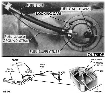 |
| 3. The factory’s way of accommodating both an oil pressure gauge and warning lamp was, for years, a plumber’s nightmare - and an invitation to leakage. Many car owners, yours truly included, have concocted something similar. |  |
| 4. Oil senders have traditionally been either the familiar “dome” unit (A, 4051686) for use with a stock oil pressure gauge, or a simple 8 PSI switch (B, 4169629) for use with a warning lamp. The aftermarket has 20 PSI switches, which are “early warning” devices and a great idea - as is an aftermarket mechanical gauge. But if you want to keep your stock gauge and add a big red bulb, something new - C, 53030493 - will allow you to have both, easily and neatly. | 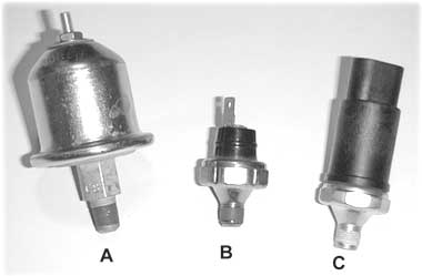 |
| 5. This photo shows which pin is which on the dual sender (53030493.) For the connector, you’ll need to visit the boneyard or auto parts store - we could find no trace of it in any Mopar parts catalogs. | 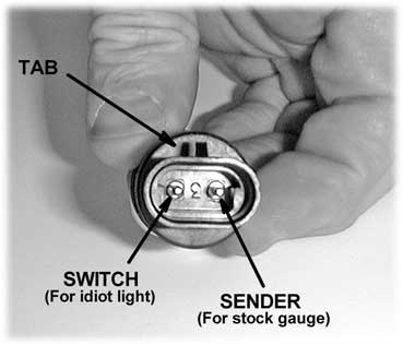 |
| 6. This piece of junk, also seen in fig. 7, is the cause of most “dead gauges” and “pegged gauges” problems, as well as causing wide swings of the needle when there’s no true pressure, temperature, or fuel level change. It has to go! | |
| 7.
Most Mopar instrument clusters have a printed circuit board. In this
case, the regulator simply plugs in. Some (very few) have the regulator
integral with one of the gauges, fuel or temperature. In this case, to
upgrade, you’d need to surgically chop out the regulator section. This
would require some creativity, but in no case is it difficult. To begin the conversion, toss the stock regulator, and, if present, the old metal-case suppression capacitor. |  |
| 8. Some other clusters (E-body is a prime example) have no circuit board - just a mish-mash of gauge-to-gauge and gauge-to-regulator wiring. These setups are very easy to modify. |  |
 9.
The stock regulator, item #1, is replaced by a small silicon chip
(#2) in the industry as a “7805". The version we need is 5 volts,
1.5 amps, positive. This is pretty common, and never costs more than a
buck. The one we used is Texas Instruments #UA7805C, obtained from
Digi-Key Electronics, and their stock number 296-1974-5-ND. Radio
Shack will also have them. A small electrolytic capacitor, any value
from 5 to 100 uF, is also needed. It must have a voltage rating of at
least 15 volts (more is fine). We used Digi-Key stock number P5999-ND,
which is 10uF @ 100V. Not critical! Its purpose is to protect the chip
from voltage spikes. 9.
The stock regulator, item #1, is replaced by a small silicon chip
(#2) in the industry as a “7805". The version we need is 5 volts,
1.5 amps, positive. This is pretty common, and never costs more than a
buck. The one we used is Texas Instruments #UA7805C, obtained from
Digi-Key Electronics, and their stock number 296-1974-5-ND. Radio
Shack will also have them. A small electrolytic capacitor, any value
from 5 to 100 uF, is also needed. It must have a voltage rating of at
least 15 volts (more is fine). We used Digi-Key stock number P5999-ND,
which is 10uF @ 100V. Not critical! Its purpose is to protect the chip
from voltage spikes.
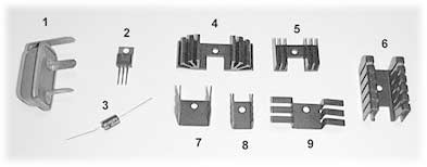
These chips can get pretty warm, so you’ll need a small heat sink. These are also under a buck each! #4 and #5 are extrusions, and are probably the best. But any will do the job, pick the one that will be easiest to mount to your cluster. Here’s the Digi-Key numbers:
Remember, you only need one of these! |
|
| 10. Your first task is to gently bend the outer pins at a 45-degree angle as shown. Note that the pin we’re bending is the input, which can handle anything from about 7 to 20 volts! The center pin is also connected to the mounting tab, and is ground. The right-hand pin is the 5-volt regulated out. This voltage is rock-steady! | 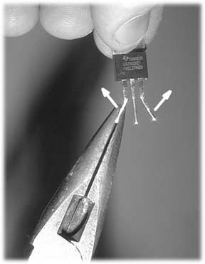 |
| 11. Begin by stripping one end of three lengths (6 inches each, or so) of ordinary insulated wire. Almost any wire will do, from 20 to 26 gauge, stranded or solid. | 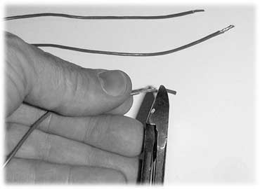 |
| 12. Now wrap and solder one wire to each lug on the new solid-state regulator. Use rosin core solder only! A small-wattage iron or gun (20 to 100 watts) is fine. Don’t go crazy with heat! Be sure the wires and lugs don’t touch each other. You can then cover each lug with heat-shrink tubing if you’d like. (We didn’t bother). | 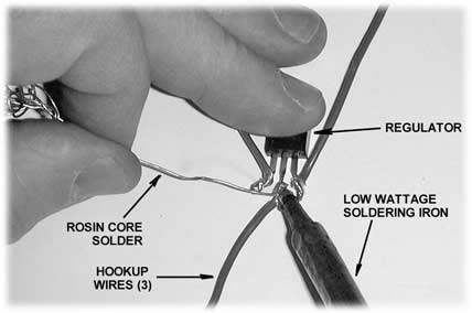 |
| 13. Now solder the small capacitor, negative to ground, positive to the 12-volt input terminal (center). Note the three locations - ground, input, and 5-volt output. | 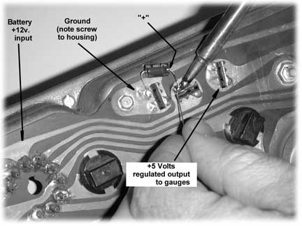 |
| 14. Mount the new device to your chosen heat sink and screw it to some convenient point. Be sure no wires touch, then connect the three wires as shown. Refer to figure 10 again if you’re unsure. | 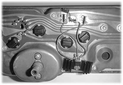 |
There are more ways to do this job. You could “gut” the stock regulator and mount the new chip, cap, and heat-sink to it. Then it would be a plug-in swap! With non-printed-circuit-board clusters, this would probably be the easiest approach. With reg-in-gauge versions, you’ll have to fly blind; just remember the “pinouts” shown in fig. 10. You’re done, expect rock-steady gauges from now on.
SOURCE: Digi-Key Corp., PO Box 677, Thief River Falls, MN 56701, Orders (800) 344-4539
![]() Home - Cars - Engines - History - Resources - Repairs - Reviews - Books - News - Search
Home - Cars - Engines - History - Resources - Repairs - Reviews - Books - News - Search
Please read the terms of use. Need market research?.
Mopar, Dodge, Jeep, Plymouth, and Chrysler are trademarks of
DaimlerChrysler, AG. We are not affiliated with DaimlerChrysler. We are
not responsible for the consequences of actions taken based on this
site and make no guarantees regarding validity or applicability of
information, opinions, or advice. The Webmaster is not an expert.
Copyright © 1999-2000, David Zatz; copyright © 2001-2004, Allpar LLC. All rights reserved. Recommend this page!
Riding the Roller Coaster: A History of the Chrysler Corporation
Howell Automotive for Mopar sport-compact performance!
We hope you liked Allpar's Jeep, Plymouth, Chrysler, and Dodge car, truck, and minivan information.