Dodge Ram pickup truck
Cummins diesel engine valve adjust procedure
| B Series Valve Clearance Adjustment |
For additional information, see TDR Issue 5
- Summer 1994,
Ram service Manual, Cummins B Series Service Manual
|
Tools needed:
- 14mm wrench
- 15mm wrench
- 19mm wrench
- Large Flat blade screwdriver
- soft mallet or wood block
- Engine Barring Tool
- Long 1/2" drive wrench
- Torque Wrench
- feeler gauge
|
 |
| NOTE: The Cummins Midrange Performance Tool Kit (P/N
3399869) contains all of the tools required for an oil and oil filter change,
a fuel filter change, and a valve-lash adjustment - including the special
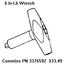
barring socket. Also available from Cummins is a 6 in-lb valve adjust torque
wrench which sets a consistent load on the feeler gauge. This tool is handy,
but not necessary. |
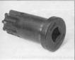
| Engine Barring tool sources: Cummins # 3377371;
Snap On # YA9565; KD tools # 3824 |
|
Valve clearance should be adjusted when the engine
is cool (below 140 F or 60 C).
Intake Clearance: 0.010", 0.254
mm
Exhaust Clearance: 0.020", 0.508 mm
Service Interval : 24,000 miles
|
| 1. |
On 1989-1991 models, remove the turbocharger-to-intake crossover
pipe.
On 1994-1998 models, remove the plastic cover over the individual
valve covers. |
| |
 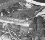 |
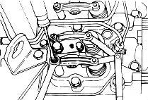
| 2. |
Remove all 6 valve covers (15mm). If a cover sticks, tap it gently
with a soft mallet or wood block - Do not pry the cover loose. |
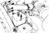
| 3. |
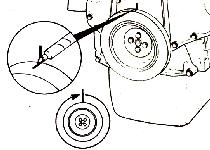
Remove the rubber plug from the front of the bellhousing on
the passenger side. |
| 4. |
 Insert
the barring tool into the bellhousing hole. Insert a 1/2 drive wrench
into the barring tool, and turn the crankshaft slowly, while watching
the valve train. Press the timing pin to locate Top Dead Center (TDC)
for cylinder No.1. Insert
the barring tool into the bellhousing hole. Insert a 1/2 drive wrench
into the barring tool, and turn the crankshaft slowly, while watching
the valve train. Press the timing pin to locate Top Dead Center (TDC)
for cylinder No.1. |
| |
If no barring tool is available, the crankshaft
may be turned with a 22 mm socket on the alternator pulley bolt. Rotate
the engine clockwise when viewing from the front of the truck.
This method turns the engine backwards, so make sure you are adjusting
the correct valves. |
| |
You can also turn the engine with a 15mm
socket on one of the harmonic balancer pulley bolts. |
| |
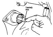
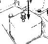
Note: The timing pin is located at the back of the
gear housing and below the injection pump. Fitting the timing pin
into the hole in the crankshaft is tricky, watch the valve train until
the #1 exhaust valve closes, then turn the crankshaft about 90 degrees.
If the timing pin will not engage, spray it with some penetrating
oil to loosen it. |
 |
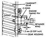
| 5. |
When the pin engages the hole in the camshaft gear,
cylinder No. 1 is at TDC on the compression stroke. Be sure to
disengage the timing pin after locating top dead center. |
 |
| 6. |
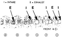
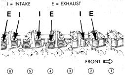
Adjust the clearance for these valves:
- #1 - I & E
- #2 - I
- #3 - E
- #4 - I
- #5 - E
|
 |
| |
- Adjust Intake valves for 0.010" clearance
- Adjust Exhaust Valves for 0.020" clearance
From the Cummins B series Operation and Maintenance manual: The
adjustment is correct when some resistance is felt when the feeler
gauge is slipped between the valve stem and the rocker lever.
|
 |
| 7. |
Tighten the lock nut, torque to 18 ft-lb (24 Nm) and
check the valve lash again. When the feeler gauge slides between the
valve stem and the rocker lever with "some" resistance,
the clearance is correct. |
| 8. |
Mark the crankshaft pulley and rotate the crankshaft
360 degrees. Caution: Make sure the timing pin is disengaged.
Rotating the crankshaft with the timing pin engaged will beak the
pin and can result in engine damage. |
 |
| 9. |
Adjust the clearance for these valves:
- #2 - E
- #3 - I
- #4 - E
- #5 - I
- #6 - I & E
|
 |
| 10. |
Tighten the lock nut, torque to 18 ft-lb (24 Nm) and
check the valve lash again. When the feeler gauge slides between the
valve stem and the rocker lever with "some" resistance,
the clearance is correct. |
| 11. |
Inspect the rubber o-rings on the bolts and replace any o-rings
that are cracked or damaged. The valve cover gaskets are usually OK
and may be reused many times. If any are damaged, be sure to replace
then with the black gaskets, not the gray gaskets that appear similar.
Install the valve covers and tighten the capscrews to 18 ft-lb (24
Nm).. |
 |
| 12. |
Install the plastic cover or crossover pipe on appropriate models. |
|
|
A short version:
- Let the engine cool 4 hours and remove the valve covers.
- Use the alternator bolt to turn the engine backwards.
- When a rocker arm is not on the lift lobe of the cam, adjust the intake
valves for 0.010" clearance and the exhaust valves for 0.020".
- Loosen the lock nut
- Adjust for the correct clearance - a slight drag will be felt on the feeler
gauge
- Torque the locknut to 18 ft-lb.
- Recheck the clearance - the drag on the gauge should be the same.
- Continue turning the engine and adjusting valves until all have been completed
(put a small plastic sandwich bag on each valve when it has been done).
- When adjustment has been completed, remove the plastic bags from the valves
and replace the valve covers
Another short version:
Put the engine on #1 compression stroke, use the timing pin to locate this
the first time then mark your harmonic balancer. Set the first 3 valves, skip
2 valves, set 2 valves, skip 2 valves, set the next valve. Rotate engine 360
degrees, until your mark lines up again, now you will be on exhaust stroke of
#1 cyl., compression stroke of #6 cyl. Skip the first 3 valves, set the next
2 valves, skip the next 2 valves, set the next 2, skip the next valve, set the
last 2.
Another short version:
Crank engine around with ratchet wrench and 15mm socket on one of the bolts
that holds the pulley on the vibration damper, until # 5 (the next in the firing
order) intake valve goes down and just starts to come back up,STOP! Adjust #
1 intake and exhaust valves at this time. Make sure the feeler gage just sides
under the rocker arm smooooothly after you have retightened the lock nut. If
its too tight or too loose, try to loosen the lock nut and the adjuster together
until the lock nut is loose and then adjust the screw either tighter or looser
and retighten them together again. It will take a little time to catch on to
it, but you will. The intake valve is in the front and the exhaust is in the
back on each cylinder. Now, turn the engine over until # 3 ( the next in the
firing order) intake valve goes down and just starts to come back up,STOP. Adjust
# 5 the same way you did # 1. Now turn engine over until # 6 (next in order)
intake valve starts back up,STOP adjust # 3. Just follow the firing order back
to # 1.
Another short version:
Here's a tip for doing valve lash adjustment that will make it go faster...
1. Turn over the motor with a 7/8" socket on the alternator pulley. One other
thing, to locate TDC @ #1, watch #6 until it's at crossover (one rocker going
up, the other going down at the same time). This is called the "companion cylinder"
method. Adjust the proper valves, then rotate the engine over until #6 is at
TDC, which means #1 will be at crossover. Gap the intake valves at 0.010" and
the exhaust at 0.020."
When at TDC for #1, check: Intake 1, 2, and 4 Exhaust 1, 3, and 5
When at TDC for #6, check: Intake 3, 5, and 6 Exhaust 2, 4, and 6
Last Update: February 7, 2000